In FPC (Flexible Printed Circuit) assembly, the magnetic carrier is essential because FPC is too thin and flexible to be processed directly by SMT (Surface Mount Technology) lines. It transforms the “soft” board into a “rigid” one.
Base Plate (Bottom Carrier):
Material: Usually made of Synthetic Stone (to prevent ESD and withstand heat) or high-grade aluminum/stainless steel.
Function: It serves as the foundation. High-strength permanent magnets are embedded inside the base plate to provide clamping force.
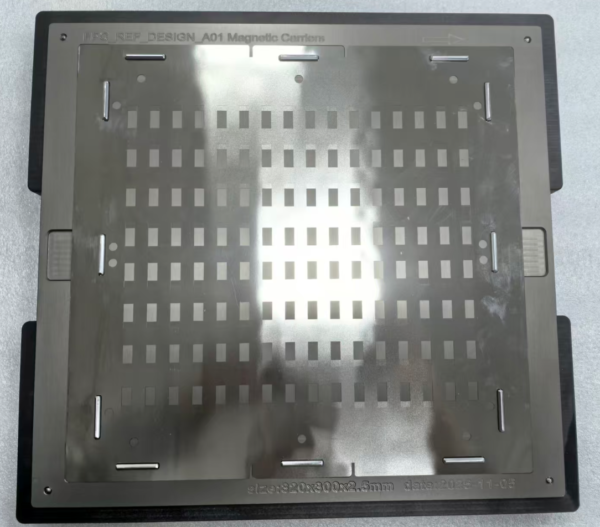
Function: This plate features precision-cut windows that match the FPC’s soldering areas. It is attracted by the magnets in the base plate, “sandwiching” the FPC to ensure it remains perfectly flat.
Positioning Pins (Dowel Pins):
High-precision pins installed on the base plate.
Function: These pins align with the FPC’s tooling holes and the cover plate’s registration holes to ensure an alignment accuracy of typically Function: These pins align with the FPC’s tooling holes and the cover plate’s registration holes to ensure an alignment accuracy of typically Function: These pins align with the FPC’s tooling holes and the cover plate’s registration holes to ensure an alignment accuracy of typically 0.05mm.
2. The Loading Jig (Base Station)
The Loading Jig is not a carrier itself, but a stationary assembly fixture used to assist operators or robots in accurately mounting the FPC onto the magnetic carrier.
Profiled Base: A cavity or “pocket” CNC-machined to match the exact outer contour of the magnetic carrier.
Guide Pillars: Vertical pillars that ensure the magnetic cover plate descends perfectly straight onto the base plate, preventing the magnets from “snapping” the cover down unevenly and damaging the FPC.
Poka-Yoke (Error Proofing): Features that prevent the FPC or carrier from being loaded in the wrong orientation.
3. Working Principle and Process
The workflow follows a systematic cycle to ensure precision and repeatability:
Step 1: Carrier Loading
The empty Magnetic Base Plate is placed into the Loading Jig. The jig secures the base plate in a fixed, repeatable position.
Step 2: FPC Placement
The FPC is placed onto the base plate. The Positioning Pins on the base plate pass through the FPC’s alignment holes. At this stage, the FPC is located but might still be warped or wavy.
Step 3: Cover Attachment
The Magnetic Cover Plate is lowered using the Loading Jig’s guide system.
Magnetic Clamping: As the cover approaches the base, the magnetic field pulls it down, applying uniform pressure across the FPC.
Flattening: The cover plate flattens the FPC against the synthetic stone surface, eliminating any air gaps or wrinkles.
Step 4: SMT Processing
The assembled unit (Base + FPC + Cover) moves through the production line:
Solder Paste Printing: The stencil sits on top of the cover plate, and solder is applied through the windows.
Pick and Place: Components are mounted onto the exposed FPC pads.
Reflow Soldering: The entire assembly goes through the oven. The magnets must be high-temperature resistant (usually Samarium Cobalt magnets) to maintain their pull at $260^{\circ}\text{C}$.
4. Key Advantages
Feature
Description
Planarity
Prevents FPC “bounce” or vibration during printing, which avoids solder bridging.
Heat Shielding
Synthetic stone has low thermal conductivity, protecting the FPC from localized overheating.
Efficiency
Allows multiple small FPCs to be processed on a single large carrier (Panelization).
Durability
Designed for thousands of thermal cycles without losing magnetic strength or physical shape.


